Deprecation warning
This website is now archived. Please check out the new website for Centre for Intelligent Systems which includes both A-Lab Control Systems Research lab and Re:creation XR lab.
On this site, please find older content as well, such as list of older completed projects and publications.
- 3D Crane
- ABS
- Magnetic Levitation
- Multi Tanks
- Pendulum & Cart
- Tower Crane
- Two Rotor System
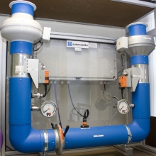
- Pressure Kit
- Heater Kit
- Virtual Coupled Tanks
- Kinect for Windows
- 3D Printer
- Ultimaker 2 Extended
- Oculus Rift DK2
- Raspberry Pi
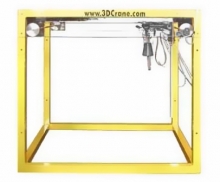
The three-dimensional model of industrial crane is a highly nonlinear MIMO system equipped with a dedicated system of sensors unique 2D angle measuring unit. The system is fully integrated with MATLAB and Simulink and operates in real-time. The software enables rapid prototyping of real-time control algorithms. The C-code writing is not required. 3D Crane is delivered with the library of basic controllers. The model has three control DC motors and five position measuring wheel encoders. An example of the 3D P controller is shown. The Real Time Workshop and Build Model items chosen from the pull-down menus execute the RTW routines. As a result one obtains the executable file which operates as a real-time controller after connecting it to Real Time Windows Target.
The automotive engineering system to control the wheel slip Antilock Braking Systems are designed to optimize braking effectiveness while maintaining car controllability. The ABS model is driven by a flat DC motor steered from a PC. There are three encoders measuring the rotational angles of two wheels and the lever angle of the car wheel suspension.
At the beginning of an experiment the wheel simulating the relative road motion is accelerated to a given threshold velocity. The car wheel accelerates following the rotational motion of the “road” wheel. At the threshold a braking procedure starts. If the car wheel becomes motionless it means that it remains in slip motion (the car velocity is not equal to zero) or is absolutely stopped. The less the slip the better car control. One of the pre-programmed slip control algorithms can be applied.
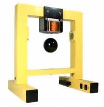
The Magnetic Levitation System (MLS) is a nonlinear, open-loop, unstable time varying frictionless dynamical system. The basic principle of MLS operation is to apply the voltage to an electromagnet to keep a ferromagnetic sphere levitated. Moreover, the sphere can follow a desired position value varying in time. The coil current is measured to explore identification and multi loop or nonlinear control strategies. To levitate the sphere a real-time controller is required. The equilibrium stage of two forces (the gravitational and electromagnetic) is maintained by the controller to keep the sphere in a desired distance from the magnet. The system is fully integrated with MATLAB/Simulink and operates in the real-time in MS Windows. The PC equipped with the RT-DAC/PCI I/O board communicates with the power interface. The user can create his own controller in a fast and easy way.
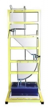
The Multitank System comprises a number of separate tanks fitted with drain valves. Two of the tanks have varying cross sections. These introduce nonlinearities into the system. A variable speed pump is used to fill the upper tank. The liquid outflows the tanks due to gravity. The tank valves act as flow resistors. The area ratio of the valves is controlled and is used to vary the outflow characteristics. Each tank is equipped with a level sensor.
The general objective of the control is to reach and stabilize the level in the tanks by an adjustment of the pump operation or/and valves settings. This control problem can be solved by a number of level control strategies ranging from PID to adaptive and fuzzy logic.
The Multitank System is designed to operate with an external PC-based digital controller. The computer communicates with the level sensors, valves and pump by a dedicated I/O board and the power interface. The I/O board is controlled by the real-time software which operates in the MATLAB/Simulink RTW/RTWT environment. A dedicated library of controllers and Simulink models support the Multitank system.
The Pendulum & Cart System consists of a pole mounted on a cart in such a way that the pole can swing freely only in the vertical plane. The cart is driven by a DC motor. To swing and to balance the pole the cart is pushed back and forth on a rail of limited length. The purpose of the inverted pendulum control algorithm is to apply a sequence of forces of constrained magnitude to the cart such that the pole starts to swing with an increasing amplitude and it does not override the ends of the rail. The pole is swung up to achieve a vicinity of its upright position. Once this has been accomplished, the controller is maintaining the pole vertical position and is bringing the cart back to the centre of the rail. The system operates directly in the MATLAB/Simulink environment. The user obtains ready pre-programmed experiments in the real-time using the RTWT toolbox. He also generates his own controller in a very fast and easy way using Simulink and library of drivers. The forth order, nonlinear and unstable mathematical model of the system is included.
The three-dimensional laboratory model of tower crane corresponds to a modern structure of cranes that give the best combination of height and lifting capacity. The laboratory model is a highly nonlinear MIMO system equipped with a dedicated system of sensors – unique 2D angle measuring unit.
Every tower crane consists of the jib and counterjib. Both are mounted to the turntable, where the slewing bearing and slewing machinery are located. The counter-jib carries a counterweight and the jib suspends the load from the trolley. In our model the turntable is located at the top of the tower – a special plastic-metal slewing ring is used. The system is fully integrated with MATLAB/ Simulink and operates in the real-time. A number of pre-programmed control experiments are included. They constitute a proper basis to construct own new algorithms of a user. The rapid prototyping of real control algorithms becomes an easy task (none C code writing is required). There are three control drives (the DC motor equipped with a gear) and five angular-position sensors (encoders). The jibs rotate driven by the first powerful drive. The trolley on the jib rail with an adjustable clearance is pushed back and forth by the transmission belt and the second drive. The lifting load is operated by the third drive. The typical control goal is to track a desired threedimensional trajectory (i.e. operate the load in a prescribed manner) and simultaneously keep the load at the minimal amplitude of swinging.
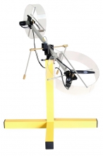
Two Rotor Aerodynamical System (TRAS) is a laboratory set-up designed for control experiments. In certain aspects its behaviour resembles that of a helicopter. From the control point of view it exemplifies a high order nonlinear system with significant cross-couplings.
TRAS consists of a beam pivoted on its base in such a way that the beam can rotate freely both in the horizontal and vertical planes. At both ends of the beam there are rotors (the main and tail ones) driven by DC motors. A counterbalance arm with a weight at its end is fixed to the beam at the pivot. The state of the beam is described by four process variables: horizontal and vertical angles measured by encoders fitted at the pivot, and two corresponding angular velocities. Two additional state variables are the angular velocities of the rotors, measured by speed sensors coupled with the driving DC motors. In a real helicopter the aerodynamic force is controlled by changing the angle of attack. In the laboratory set-up the angle of attack is fixed. The aerodynamic force is controlled by varying the speed of rotor. Significant crosscouplings are observed between actions of the rotors. Each rotor influences both position angles. A design of stabilising controllers for TRAS is based on decoupling. The TRAS system has been designed to operate with an external, PC-based digital controller. The control computer communicates with the position, speed sensors and motors by a dedicated I/O board and power interface. The I/O board is controlled by the real-time software which operates in the MATLAB/Simulink RTW/RTWT environment. A pre-programmed library of controllers and Simulink models supports the TRAS system.
The laboratory plant consists of a heater and a fan, actuated by pulse-width modulation through high power MOSFET transistors and controlled from the Simulink environment by means of a virtual serial port established over a USB connection. This prototype has been designed and developed in our laboratory in the context of a Master’s thesis project with the main design goal being related to teaching. Thus, the plant can be used to simulate heating processes while the cooling fan may be regarded as a disturbance.
The Virtual Coupled Tanks System (VCTS) represents a physical implementation of an industrial liquid level control process. However, the liquid tanks are emulated by means of LCD screens. The unit can work in standalone mode, or be controlled from a PC running appropriate software. The process is modelled on an embedded device with a high degree of accuracy. The device itselt can be seen as an intermediate step between pure software simulations and real-life control objects, as it provides the physical presense of a coupled tanks system, yet requires no maintenance as a real-life device would. This is a particular prototype, and it is possible to build such systems on demand for the purposes of student/control engineer training.
Kinect (codenamed in development as Project Natal) is a line of motion sensing input devices by Microsoft for Xbox 360 and Xbox One video game consoles and Windows PCs. In our laboratory we have one Kinect for Windows v1. It may be used to develop motion control systems for, e.g., available laboratory objects.
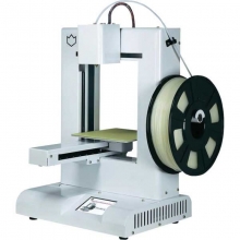
The IdeaWerk WT200 combines performance and convenience like no other printer in its class. It assembles easily and uses patented technology to make 3D printing simple and efficient for all types of projects. Its design is sturdy enough to handle even the toughest jobs, but lightweight enough to be portable. The printing process is controlled with a touch screen panel for file selection and job initiation. Using an advanced algorithm to improve the quality of printed objects, the IdeaWerk can print with detailed precision at a 0.18 mm layer thickness. Compatible with the latest versions of Windows and Mac OS, as well as many previous builds, the IdeaWerk will link in with your current technology suite. No needs to purchase additional software or accessories, just assemble, connect and begin printing immediately.
Ultimaker 2 is the successor to the Ultimaker Original and was released in September 2013. MAKE magazine classified the Ultimaker 2 as the "best open-architecture 3D printer of 2014" and named it runner-up in the category "Prosumer FFF".
Frame: Open
Highest Resolution: 20 microns
Materials Supported: ABS, PLA
Maximum Build Area: 30.48 x 22.86 x 22.61cm (HWD)
Number of Extruders: 1
SD Card Slot: Yes
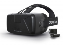
The Oculus Rift Development Kit 2 is the latest development kit for the Oculus Rift with a low-persistence OLED display and low-latency positional head tracking.
In the context of the laboratory the device is meant to be initially used for immersive 3D control environment/operator interface design, with particular focus on control engineer training.
The Raspberry Pi is a low cost, credit-card sized computer that plugs into a computer monitor or TV, and uses a standard keyboard and mouse. It is a capable little device that enables people of all ages to explore computing, and to learn how to program in languages like Scratch and Python. It is a perfect platform for embedded system development, including distributed control systems.
Our laboratory has three sets of Raspberry Pi's with Gertboard extension boards, WLAN USB dongles for wireless communication, and camera modules.

